Inputs and Outputs
What Are Inputs and Outputs?
Inputs Explained
Inputs are electrical wire connections on your GPS tracker that receive positive voltage signals from external devices. The input is activated by receiving a +12V or +24V signal on the corresponding Input wire, where the tracker and external device are on the same common ground. Depending on what you connect your input to, the signals that can be received can include:
- Panic buttons for raising emergency alerts
- Door sensors or lights for security monitoring if a door is opened
- Custom sensors for specific monitoring needs
- Monitoring of electrical components and devices in the vehicle, such as the operation of winches, fuel pumps, PTO or similar
When an input is triggered (e.g., a panic button is pressed, a pump turns on), your GPS tracker can detect this and:
- Send instant notifications to your phone
- Trigger alerts in your Track My Ride dashboard
- Log the event for future reference
Outputs Explained
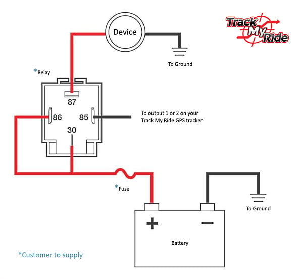
Outputs allow your GPS tracker to control switching on and off an external device or electrical circuit. Outputs on Track My Ride GPS tracking hardware operate as an Open Collector, this is a switchable path to ground. Outputs do not provide a power source. Common uses include:
- Activating warning lights or sirens
- Triggering audible alarms
- Controlling auxiliary systems (e.g., warning beacons)
- Operating powered accessories

Critical Safety Notice ⚠️

- Creates serious safety risks
- Power steering and brakes will be lost if the vehicle's engine is remotely immobilised
- Remote engine immobilisation while a vehicle is at speed may directly lead to an accident, causing loss of life
- May violate local regulations and laws
- Could result in vehicle damage
- Could result in your vehicle being stranded, and unable to be unimmobilised due to poor local mobile network signal strength
Professional Installation Requirements
All input and output connections require professional installation by a qualified Auto-Electrician because:
- Vehicle electrical systems are complex and varied
- Incorrect installation can damage your vehicle's electronics
- Professional installation ensures proper current limiting and circuit protection
- Auto-electricians understand proper fusing and relay requirements
Technical Specifications
Voltage Specifications
- Operating Voltage: Matches vehicle system (12V or 24V)
- Input Trigger Voltage: Refer to specifications below
- Output: Switchable path to ground, up to operating voltage
- Maximum Output Current: 500mA per channel
- Recommended Operating Current: Below 400mA
- High Current Devices: Must use an automotive relay
 Exceeding the 500mA current limit on an output will permanently damage your tracker's output circuit and void your warranty. Always use relays for high-current devices.
Electrical Characteristics
| Characteristic description | Value | |||
|---|---|---|---|---|
| Min. | Typ. | Max. | Unit | |
| Supply Voltage: | ||||
| Supply Voltage (Recommended Operating Conditions) | +10 | +30 | V | |
| Digital Output (Open Drain): | ||||
| Drain current - Digital Output OFF | 120 | µA | ||
| Drain current - Digital Output ON (Recommended Operating Conditions) | 0.1 | 0.5 | A | |
| Static Drain-Source resistance (Digital Output ON) | 400 | 600 | mΩ | |
| Digital Input: | ||||
| Input resistance (IGNITION/ACC Input) | 47 | kΩ | ||
| Input resistance (DIN1) | 51.7 | kΩ | ||
| Input resistance (DIN2) | 47 | kΩ | ||
| Input voltage (Recommended Operating Conditions) | 0 | Supply voltage | V | |
| Input Voltage threshold (IGNITION/ACC Input) | 7.5 | V | ||
| Input Voltage threshold (DIN1) | 2.5 | V | ||
| Input Voltage threshold (DIN2) | 2.5 | V | ||
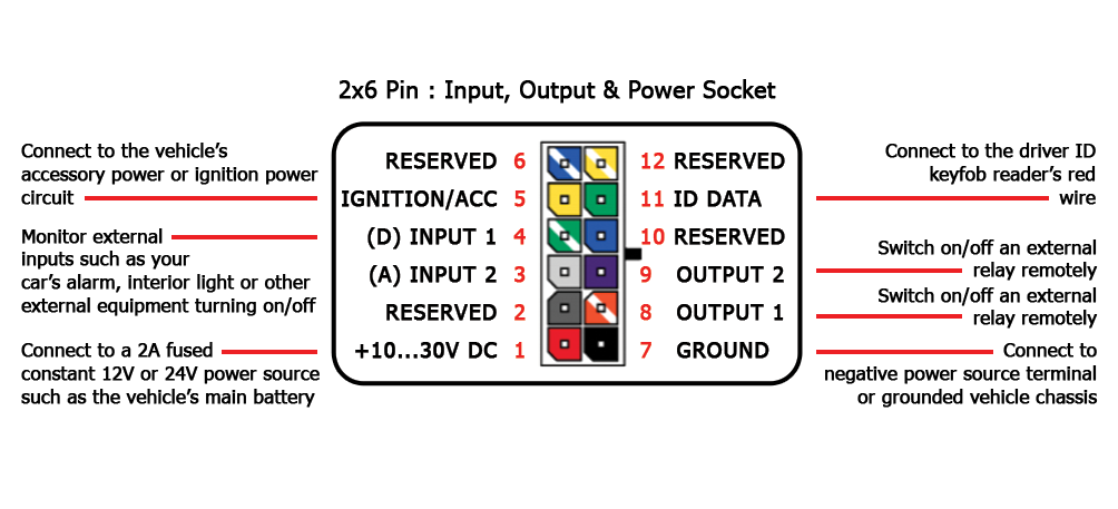
Device Pinout - TMR-S8


Detailed Configuration Guide
Accessing Vehicle Settings
- Access your Track My Ride account at https://app.trackmyride.com.au or use the Track My Ride mobile app.
- Navigate to the vehicles page
- Find the vehicle you wish to edit in the table of vehicles and click the pencil button
to the right of the row.
 If you have many vehicles on your account, you can use search field at the top right to find the right one.
 - In the vehicle editing popup that appears you have the ability to toggle the outputs On or Off for a specific duration and also select a custom action to perform when input is detected transitioning from Off to On.The input action allow you to trigger a panic notification to your account and all devices associated with your account (push notification). If you have wired up the momentary push button panic switch in the vehicle, set the input action to "Panic button".
 The panic button action operates separately to alerts, which can also be triggered based on the transition of the output from Off to On, or On to Off.
Input Configuration
In the vehicle editor, configure each input:
Input 1 and 2 Actions:
- Panic Button: Triggers emergency alerts
- No Action: No specific action is taken when the input for this vehicle transitions from Off to On. Alerts will still be raised if configured appropriately for the vehicle/tracker's inputs.
Output Configuration
Output 1 Control Method:
- Manual control (Default): Control manually via the vehicle editor popup dialog.
- Driver login reminder: When +12V is present on the Ignition/Acc wiring harness wire, then output #1 is switched On until a Driver ID keyfob is read via the Driver ID keyfob reader. A Driver ID keyfob reader must be installed in the vehicle (sold separately). See additional details at https://www.trackmyride.com.au/install
Manually Toggle an Output On/Off:

- Press the Toggle Output button to begin adjusting the output.
- The current state of the output will be indicated by the toggle that is shown, either Enabled or Disabled.
- Toggle the output switch to either Enabled, or Disabled, depending on the state you wish to change the output to.
- Choose the duration that the output should be changed for.
- Upon completion of the duration, the output will switch to the opposite of the chosen state.
Eg.
> The output #1 is toggled to Enabled for 1 hour.
> The command is queued and will be sent to the tracker the very next time it communicates with our servers.
> Upon receipt of the command by the tracker, output #1 will switch to Enabled, providing a low resistance path to ground to allow an external +12V or +24V power source to flow current through the output channel.
> After 1 hour, the output automatically changes back to the Disabled state. - Press Save to save your changes and queue your request to change the status of the output on the tracker.
- The Siren can be activated for example if the vehicle was to be stolen, to assist in creating a loud noise and draw attention to the vehicle.
- The flood light can be activated to illuminate the vehicle and it's surrounding area.
Monitoring The Status Of Your Output Change Request
Troubleshooting Common Issues
Input Issues
- No Input Detection: Check wiring and voltage levels
- False Triggers: Verify proper grounding
- Delayed Response: Check local mobile network connectivity
Output Issues
- Output Not Working: Verify current draw is under 500mA
- Intermittent Operation: Check all wiring connections
- Blown Output: May require tracker replacement if overloaded exceeding 500mA. Always use a relay to switch high current devices.
Best Practices
Safety and Reliability
- Test all functions periodically
- Inspect connections during regular vehicle service
- Keep installation documentation
- Label all connected devices
- Use proper gauge wiring for all connections
- Use a qualified auto electrician
- Use the nickname field for the outputs to remember what you have connected them to
Maintenance Tips
- Clean connections annually
- Check for loose wires
- Test emergency features regularly
- Update configuration documentation
Getting Help
If you need assistance:
- Review our online documentation above
- Contact Track My Ride support by raising a support ticket at https://support.trackmyride.com.au/portal/en/newticket
- Consult your installation auto-electrician
Related Articles
Edit a vehicle's details
Managing your vehicle's information accurately is essential for effective GPS vehicle tracking. This guide shows you how to update various vehicle parameters in the Track My Ride system, from basic details like registration numbers and odometer ...The Raw GPS report
See the Raw data we receive from your GPS unit. This is the same data we use to populate our other reports as well as the Map Page. Accessing the Report Navigate to the Reports page: From the sidebar, click on the Reports section. Select "Raw GPS ...Available reports
Track My Ride offers a variety of reports so you can easily see when your vehicles or drivers arrived at work, their top speeds, a summary of the week, and much more. The report section of Track My Ride is available in the Fleet Metrics plan. For ...Alerts for different events
Our alert system helps you stay informed about your vehicle's activities and condition. Here's a simple guide to the different types of alerts and how you can customise them. 1. Movement Alerts Type: Driving or Journeying What it Does: Tells you when ...