
The GeoBeetle Pro (TMR-S8) has two digital inputs and two open-collector outputs. An open-collector output switches a connected circuit's path to ground; it does not supply power to equipment. Configure an input to identify a wired panic button or another state change, choose how the tracker detects the engine, and send a temporary or permanent output command to professionally installed equipment.
Accurate engine detection determines when journeys start and finish, when engine alerts trigger, and when the tracker may enter a low-power state. Configure each vehicle for its installation and electrical behaviour; changing one vehicle does not affect the others or alter existing journey history.
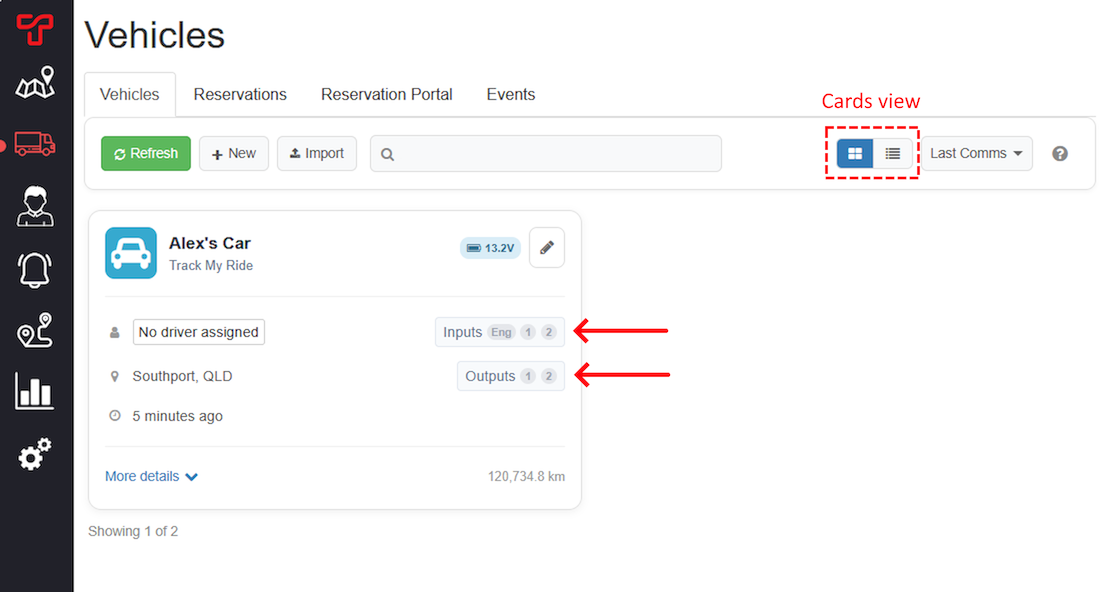
The Vehicles page shows the latest engine, input and output states. In card view, select Inputs or Outputs on the vehicle card.
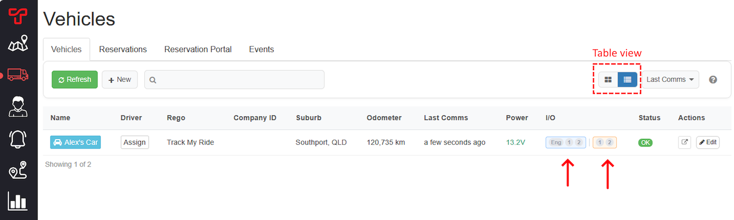
In table view, the same states appear in the I/O column. Eng is engine state, the blue 1 and 2 values are inputs, and the orange 1 and 2 values are outputs.
Before you start
- These instructions are for a GeoBeetle Pro (TMR-S8). Other trackers may have different channels or no controllable outputs.
- Ask a qualified auto electrician to install and identify each wire, relay and connected accessory. Have their channel list available before changing settings.
- Park the vehicle safely, keep people clear of connected equipment, and follow your organisation's operating procedure.
- Confirm that the tracker has recently communicated. Settings and output commands are sent over the mobile network when the tracker connects.
Never connect an accessory directly to an output unless the wiring diagram explicitly permits it. The TMR-S8 outputs are open-collector outputs, not general-purpose power supplies. Incorrect wiring or remote operation can damage equipment or create a safety risk.
Understand the TMR-S8 connections
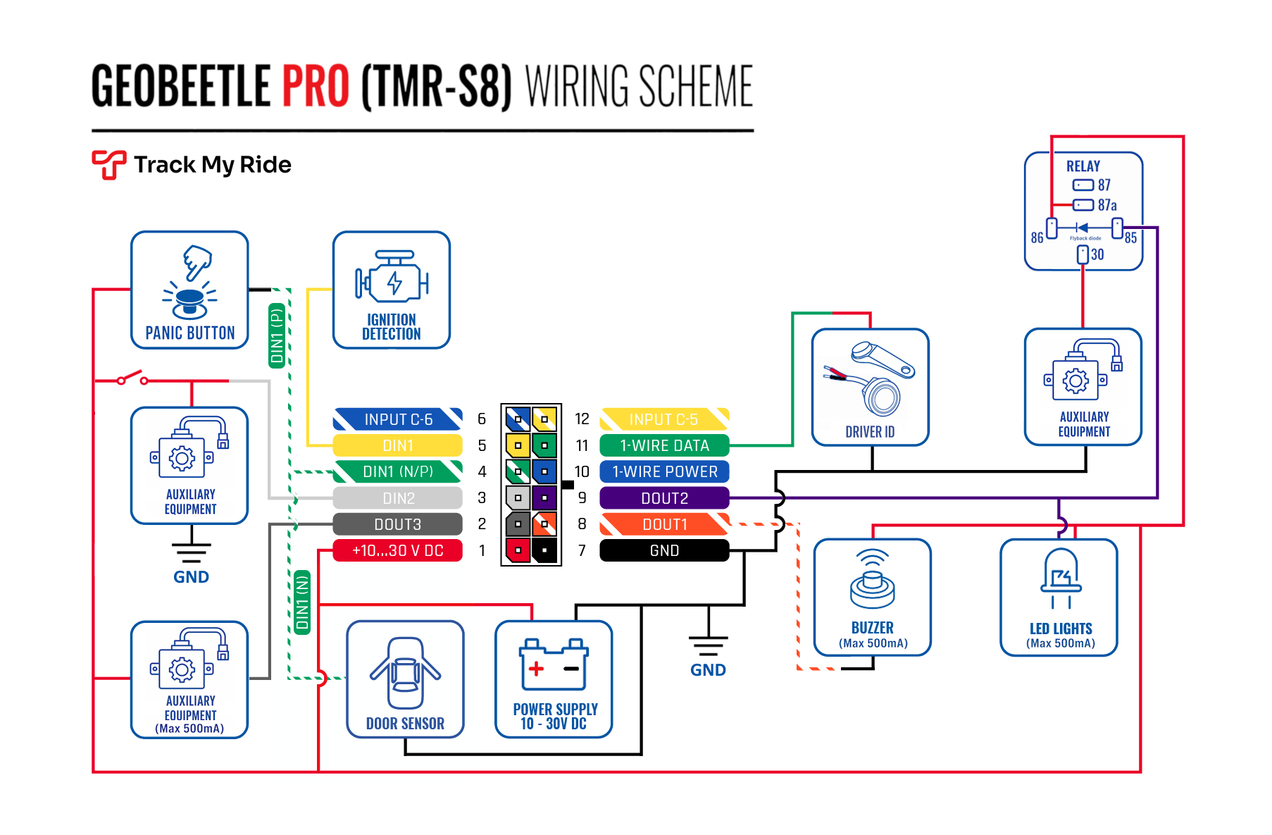
The wiring diagram identifies these channels. DIN means digital input and DOUT means digital output:
- DIN1 (N/P), harness pin 4: digital input 1. It supports positive sensing (default) or negative sensing.
- DIN2, harness pin 3: digital input 2.
- DOUT1, harness pin 8: digital output 1.
- DOUT2, harness pin 9: digital output 2.
- Ignition/Acc, harness pin 5: ignition detection input. It must use a switched 12/24 V power circuit, not a vehicle data line.
The diagram also shows example panic-button, buzzer, light, relay and auxiliary-equipment circuits. Use the circuit designed by your installer; the image is not a substitute for installation advice.
Input 1 defaults to positive sensing and is active while a switched +12 V signal is present. It can instead use negative sensing and be active while connected to ground. Input 2 uses positive sensing. Alert criteria still describe the physical low-to-high or high-to-low transition on the selected wire. A monitored accessory and the tracker must share a common electrical ground. Have a qualified installer verify the current model guide, signal and vehicle compatibility before connecting a door circuit, alarm output, horn or other accessory.
Steps
Open the vehicle editor
- Open Vehicles.
- Find the hardware-tracked vehicle and select its pencil icon or Edit action.
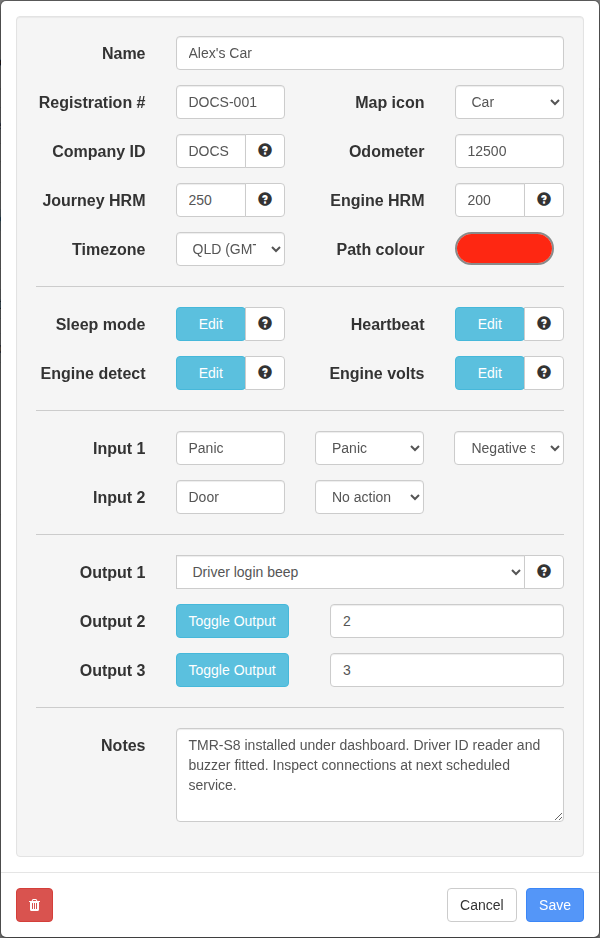
- The vehicle editor shows Engine detect, Input 1, Input 2, Output 1 and Output 2 when the assigned tracker supports them.
Configure engine detection
- Select Edit beside Engine detect.
- Choose the method that matches the vehicle and installation:
- Voltage (default): infers engine state from the tracker supply voltage. This suits most conventionally charged 12 V and 24 V vehicles.
- Ignition sense wire: uses the direct switched signal installed on the TMR-S8 Ignition/Acc wire. This is usually the most precise method for a hardwired installation.
- Motion detection: treats sustained vehicle movement as engine activity. Use it when voltage does not reliably distinguish running and parked states and no ignition wire is available.
- Voltage or Motion: considers the engine on when either voltage or motion indicates activity. This helps vehicles with smart alternators, start-stop systems, or variable charging voltage.
- Voltage or Ignition sense wire: considers the engine on when either voltage or the installed ignition wire indicates activity.
- Complete any method-specific setting displayed by the editor.
- Select Save after completing the other required changes.
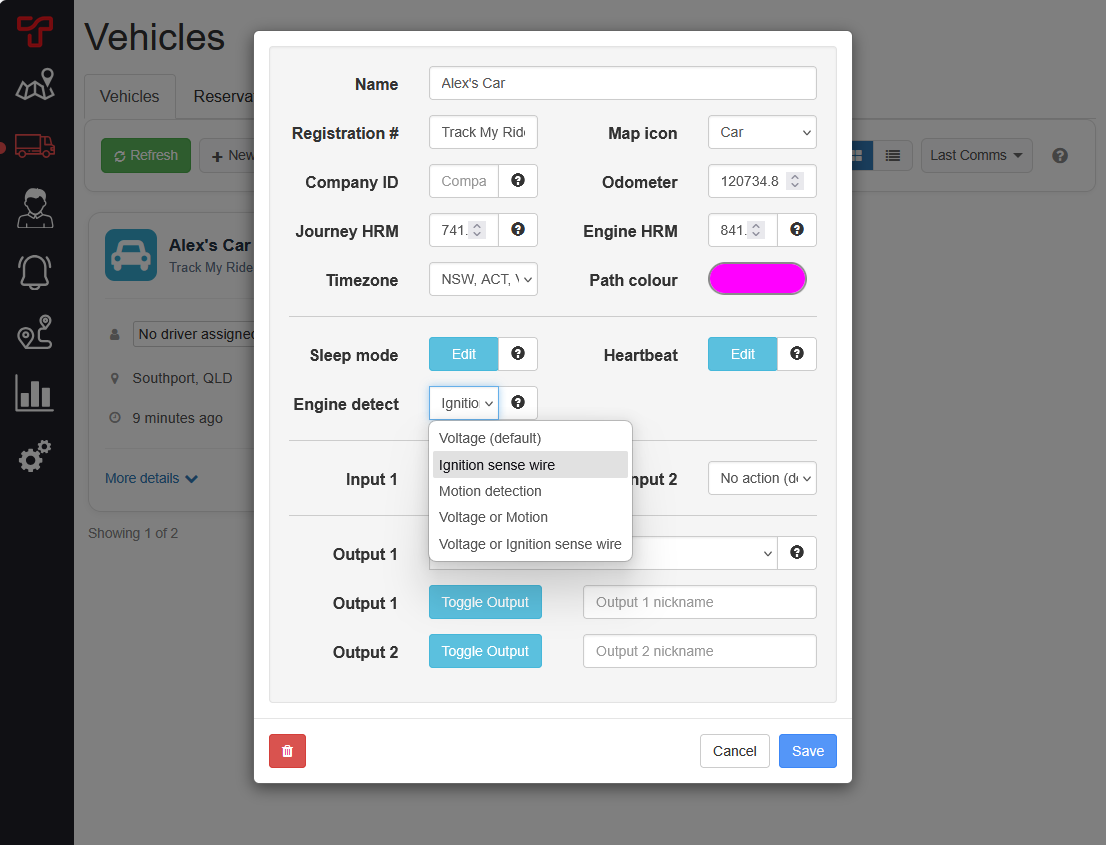
Choosing a method that does not match the physical installation can create missing or incorrect engine on/off events.
Choose the voltage threshold
The automatic Engine volts option shows its current 12 V and 24 V ranges in the editor. If the displayed range does not match the vehicle, choose a custom threshold above its stable parked voltage and below its normal running voltage.
- On Vehicles, open More details for the vehicle or use its activity-graph control.
- Open Speed & Voltage Activity and choose a period containing both parked and driving time.
- Hover over the graph and note the stable voltage with the engine off and while driving.
- Return to the vehicle editor and select Edit beside Engine volts.
- Choose a threshold between the parked and running values, then select Save.
Do not copy a threshold from another vehicle. Measure the selected vehicle because charging strategy, battery condition and electrical loads can change both parked and running voltage.
- A threshold below the parked voltage can leave the engine shown as on, create false alerts, and prevent expected sleep behaviour.
- A threshold above the running voltage can suppress journeys and engine-on alerts.
- If voltage falls while driving because of smart alternator management, use Voltage or Motion instead of lowering the threshold below the parked voltage.
Use the ignition sense wire
The Ignition/Acc wire must be installed on a circuit that is 0 V when off and 12/24 V in the state you want Track My Ride to call engine on. An accessory circuit reports on while the key is in ACC or Run; an ignition circuit can more closely follow actual engine operation.
The Ignition sense wire and Voltage or Ignition sense wire choices remain disabled until Track My Ride has received a powered ignition-wire signal from the tracker. If the wire is installed but the choices stay disabled, turn the verified circuit on, allow the tracker to communicate, and reopen the editor. Have the installer test the circuit if they remain unavailable.
Do not use an always-on source. The tracker cannot enter its expected low-power state while the ignition wire remains powered.
Understand motion detection
Motion detection is useful for electric vehicles, vehicles with unusual charging voltage, and installations without an ignition wire. It can report engine activity when a parked vehicle is transported or exposed to sustained vibration, such as on a ferry, train, transporter or active construction site. Use voltage or ignition-wire detection when that movement should not count as engine on.
Test engine detection
- After saving, wait for the tracker to connect and receive the configuration. Use Review hardware tracker commands and responses to check its queued, sent and response states.
- With the vehicle parked safely, compare the displayed Eng state with the real engine state.
- Take a short test drive and then review the journey start and finish times.
- Confirm any engine-on or engine-off alert behaves as expected before relying on it operationally.
Configure Input 1 or Input 2
- Use the installer's channel list to identify whether the physical signal is connected to Input 1 or Input 2.
- Enter an optional nickname of up to 20 letters, numbers, spaces, hyphens or underscores for the connected equipment, such as
Door,PumporPanic. Use a different, recognisable name for each connected channel. - For Input 1, confirm the installed source before changing Input 1 sensing:
- Keep Positive sensing (+12V active) for the default switched-positive installation.
- Use Negative sensing (ground active) only for a deliberately installed switched-ground circuit.
- Before changing Input 1 sensing, have the installer disconnect Input 1 from its previous switched +12 V or switched ground source. Select the new mode and confirm the warning only after it is disconnected. Input 2 cannot use negative sensing.
- Open the required input's action list.
- Select Panic button when the input is wired to the panic switch. Leave it as No action (default) if Track My Ride should not assign an application action to that wire.
- Select Save.
- Allow the tracker to connect and receive the configuration before testing the physical switch. Confirm the displayed state is inactive with the switch open and active with it closed.

Confirm a Driver ID read with a beep
On a TMR-S8, Driver login beep pulses Output 1 for 200 milliseconds after the tracker successfully reads a Driver ID from the installed iButton or RFID reader. This gives the driver short audible confirmation without enabling the ignition-based Driver login reminder.
- Confirm the Driver ID reader is working and the buzzer is connected to Output 1 (DOUT1), harness pin 8 within the 500 mA limit.
- Open the vehicle editor and set Output 1 to Driver login beep.
- Select Save, then allow the tracker to connect and receive the configuration.
- Present a Driver ID key fob or card to the reader and confirm the buzzer sounds briefly once.
- Confirm Track My Ride records the expected Driver ID. The beep confirms a successful read; it is not a substitute for checking that the credential is assigned to the intended person.
Selecting Driver login beep dedicates Output 1 to this automatic pulse. Choose Manual control (default) before using Output 1 manual controls, or choose Driver login reminder only for a compatible ignition-based reminder installation.
Turn an output on or off
Only operate an output after the installer confirms what it controls and that remote operation is safe.
- Confirm Output 1 or Output 2 is set to Manual control (default).
- Select Toggle Output for the required channel.
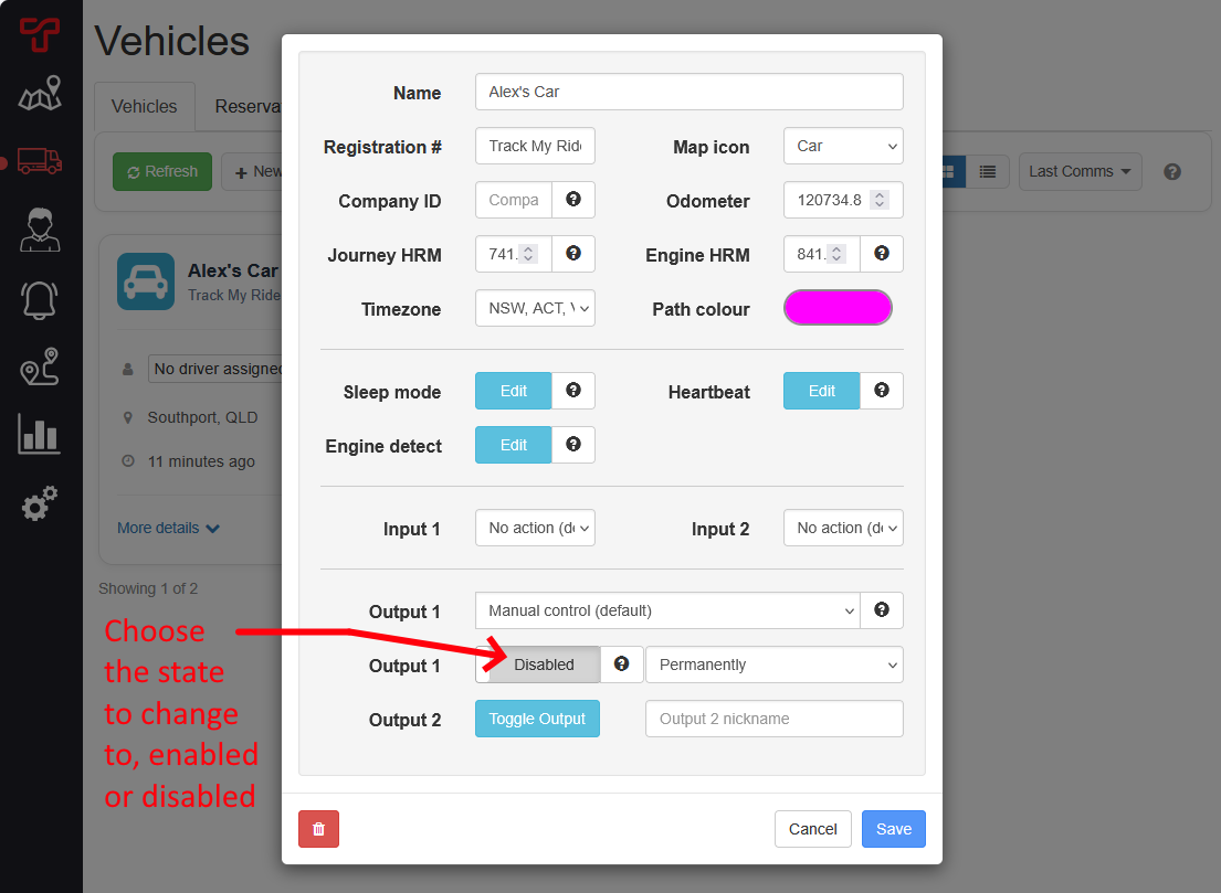
- Choose the state to send:
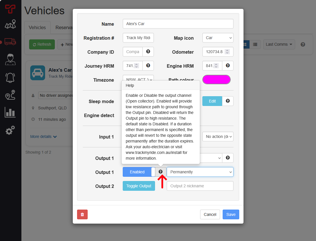
- Enabled provides the output's low-resistance path to ground.
- Disabled returns the output to high resistance. This is the default state.
- Select the help icon if you need to review the electrical behaviour before continuing.
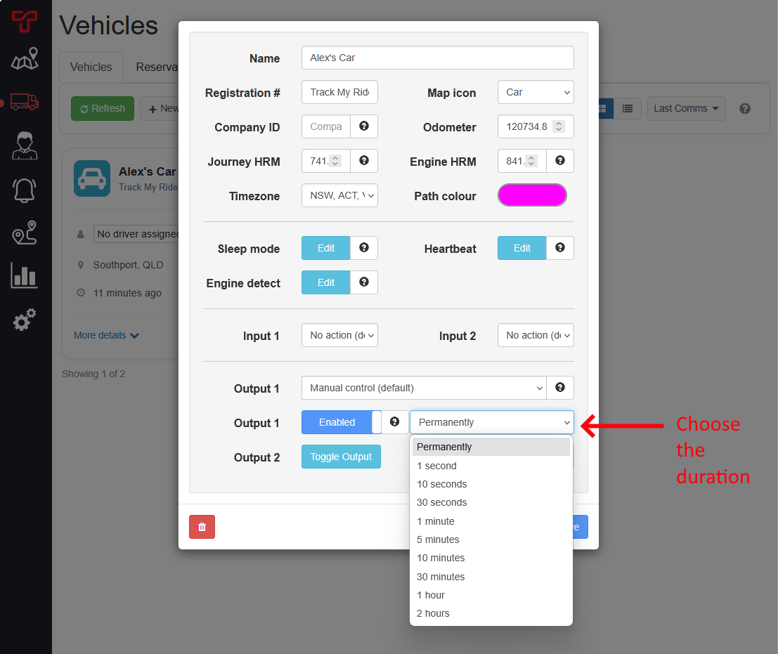
- Choose how long the output should remain in the selected state. Select Permanently, or choose a supported duration from 1 second to 2 hours. After a timed command expires, the output returns to the opposite state and remains there.
- Select Save once. Track My Ride queues the command for transmission when the tracker next communicates.
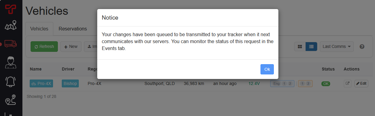
Do not repeatedly toggle or save while a command is queued. Multiple queued commands can make the final intended state difficult to identify.
Output changes are not instantaneous. A sleeping tracker normally receives them when it wakes for motion, engine/ignition activity, an input change or a supported scheduled heartbeat. Wake behaviour depends on the tracker and selected sleep mode. Connect and configure the Ignition/Acc wire when commands must reach the tracker promptly as the vehicle is turned on.
Review the output command
- Open Vehicles > Events, or read Review hardware tracker commands and responses for the complete Events-page guide.
- Find the output control row for the vehicle and channel.
- Queued in Sent at means the command is waiting for the tracker to connect.
- A date and time in Sent at means Track My Ride recorded transmission to the tracker.
- Check Response for the state and timeout reported by the tracker. For example,
Output 2: enabled Timeout:300smeans output 2 was enabled for 300 seconds, or five minutes.
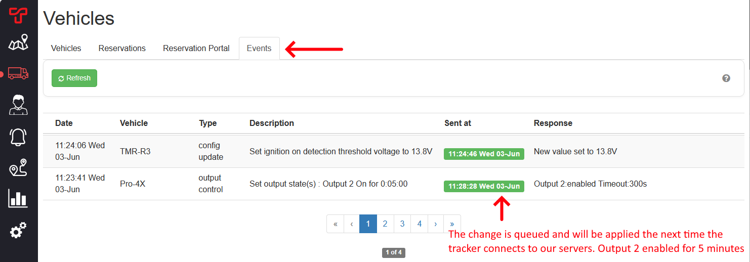
A response reports the tracker's state; it does not prove that connected equipment operated safely. Verify the physical result using your organisation's safe procedure.
Create an alert for an input change
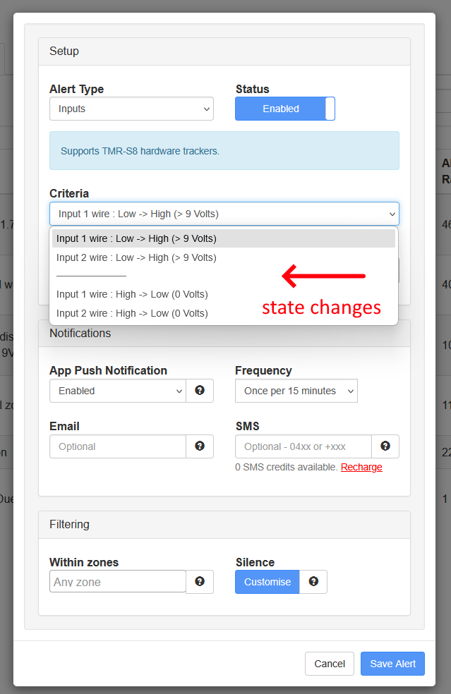
After the input configuration reaches the tracker, you can notify users when its wire changes between low and high voltage.
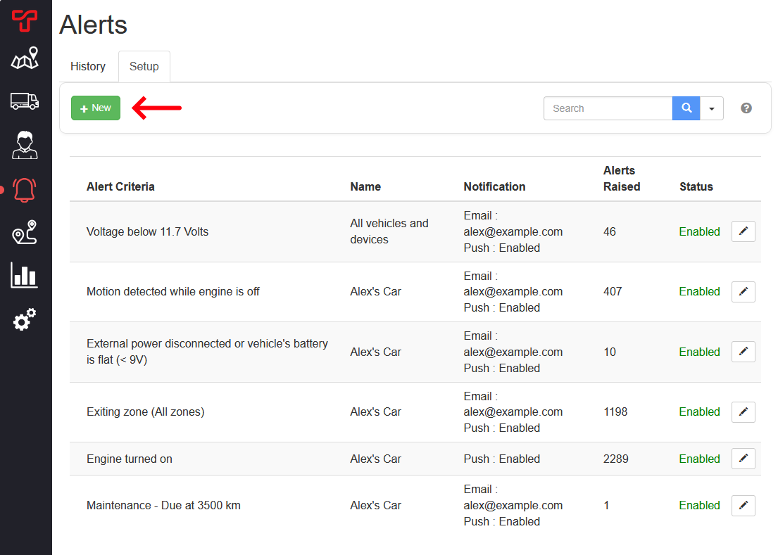
- Open Alerts > Setup and select New.
- Set Alert Type to Inputs, set Status to Enabled, and select the vehicle or devices to monitor.
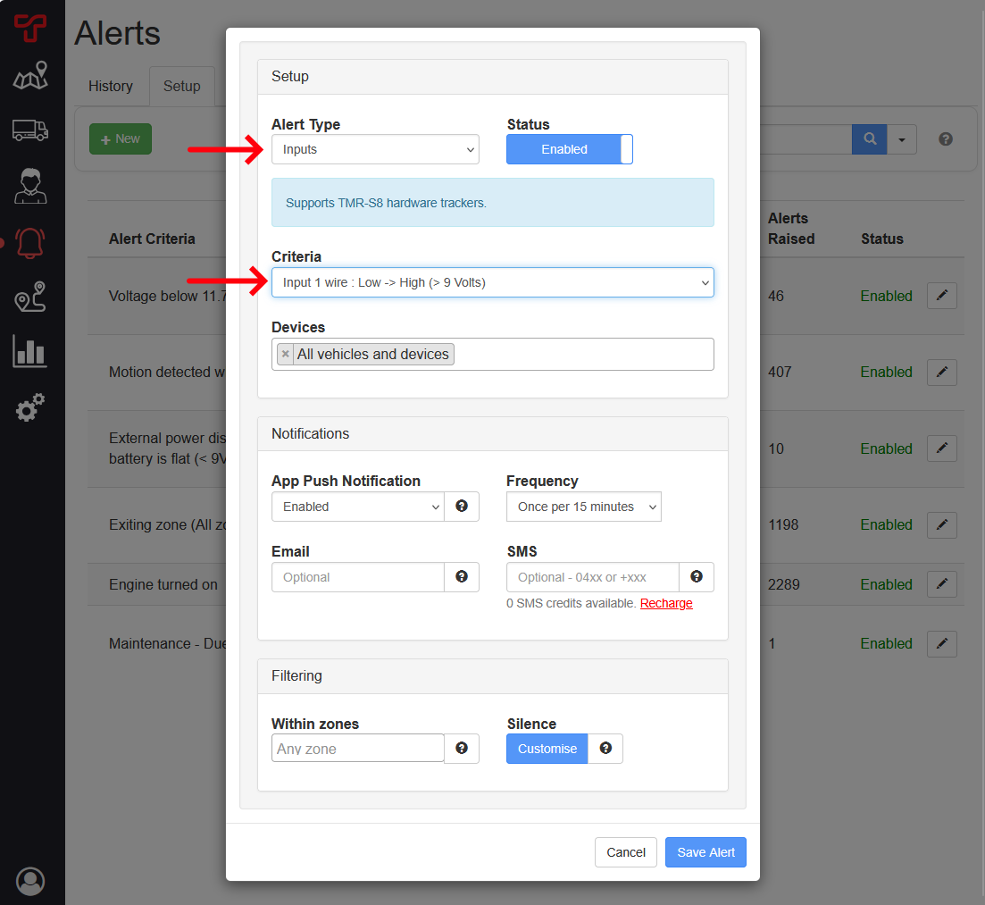
- Under Criteria, choose the physical transition that should trigger the alert:
- Input 1 wire: Low -> High (> 9 Volts)
- Input 2 wire: Low -> High (> 9 Volts)
- Input 1 wire: High -> Low (0 Volts)
- Input 2 wire: High -> Low (0 Volts)
- Configure push, email or SMS notifications, frequency, zone filtering and silencing.
- Select Save Alert, then safely test the physical input.
What happens next
Engine and input settings take effect after the tracker receives them. New input transitions can trigger compatible alerts, and output commands follow the state and duration you selected.
Use the hardware tracker command Events article whenever you need to distinguish Queued, Sent, and Responded states. Test every configured input, output and alert before relying on it for operations or safety decisions.
Troubleshooting
- The I/O controls are missing: Confirm that the vehicle has a compatible TMR-S8 tracker assigned. Other tracker models expose different controls.
- A setting or output remains queued: Check the vehicle's last communication, power and mobile coverage. Wait for the tracker to connect instead of sending duplicate commands.
- The output response is blank: Refresh Vehicles > Events after the next tracker communication. Confirm the command has a transmission time before expecting a response.
- The output reports the expected state but equipment did not operate: Stop sending commands. Have the installer check the relay, accessory power, current limits, ground path and output wiring.
- An input alert does not fire: Confirm the correct input channel and transition direction, check that the alert includes the vehicle, and verify that the physical wire crosses the documented voltage threshold.
- Input 1 shows the opposite active state: Stop testing and compare Input 1 sensing with the installed circuit. Positive sensing expects switched +12 V; negative sensing expects switched ground. Have the installer disconnect and correct the circuit before changing modes.
- An input nickname is missing or unclear: Reopen the vehicle editor, confirm the nickname is on the physical channel recorded by the installer, and use a unique name within the 20-character limit.
- Driver login beep does not sound: Confirm the tracker is a TMR-S8, Output 1 is set to Driver login beep, the configuration has reached the tracker, and the reader successfully records the Driver ID. Ask the installer to check the buzzer on DOUT1 and its current limit.
- Engine events are missing or incorrect: Ask the installer to confirm the selected detection method and physical ignition wiring. A wiring or detection mismatch is more likely than a report fault.
- Engine is always shown as on with voltage detection: Compare parked voltage with the selected threshold. Raise the threshold above stable parked voltage without exceeding normal running voltage.
- Engine is not detected with voltage detection: Compare running voltage with the selected threshold. Select a lower valid threshold, or use Voltage or Motion when charging voltage varies while driving.
- Engine is shown as on while the vehicle is being transported: Replace a motion-based method with voltage or ignition-wire detection if transport movement must not count as engine activity.
- Ignition sense wire choices are disabled: Confirm a qualified installer connected pin 5 to a switched 12/24 V circuit, power that circuit, allow the tracker to communicate, and reopen the editor.
- Detection changes do not take effect: Check Vehicles > Events for a queued configuration command and wait for the tracker to reconnect.
- An output causes an unexpected or unsafe result: Stop issuing commands, make the equipment safe, and have the installation inspected by a qualified auto electrician.