
The GeoBeetle Pro (Model TMR-S8) can use the supplied On-Board Diagnostics II (OBD-II) power cable for a plug-and-play installation or the professional wiring harness for a permanent hardwired installation. It accepts 10–30 V direct current (DC) power.
The GeoBeetle Pro package includes these wired accessories:
- A buzzer, which connects to Output 1.
- A panic switch, which connects to Input 1.
- An iButton Driver ID reader and two Driver ID key fobs, which connect as shown in the main GeoBeetle Pro wiring diagram.
Track My Ride also sells a 125 kHz radio-frequency identification (RFID) card reader separately. This optional accessory replaces the included iButton reader when you want drivers to identify themselves with compatible 125 kHz RFID cards instead of iButton key fobs. Do not connect both Driver ID readers at the same time.
The GeoBeetle Pro is not waterproof. Keep it inside a dry, protected part of the vehicle and away from direct water spray.
Before you start
Choose one installation method:
- OBD-II plug-and-play: Suitable when you need an installation that does not change vehicle wiring and the vehicle has a compatible OBD-II diagnostic port.
- Professional hardwire: Suitable for a concealed, permanent installation or when you need ignition detection and wired accessories. Installation time depends on the vehicle and accessories. A qualified automotive installer is recommended to complete this method.
You need the tracker, the cable for your chosen method, the Communication ID printed on the silver label, and access to a Track My Ride top-level account with an available hardware licence. For a hardwire installation, also have the included buzzer, panic switch and iButton Driver ID reader available. If you purchased the optional RFID upgrade, use the RFID reader and compatible cards in place of the iButton reader and key fobs.
Turn the vehicle off before installation and follow its manual when locating the OBD-II port or working near the battery.
Steps
Install with the OBD-II cable
The diagram shows common OBD-II port locations and the direction in which the power-cable plug is inserted. The exact location varies by vehicle.
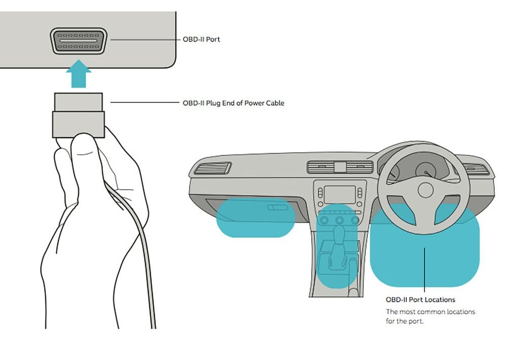
Watch Locating the OBD-II port for a short demonstration:
- Create or sign in to the top-level Track My Ride account and start tracker activation using the Communication ID. Keep the tracker powered and follow the activation status shown in the application.
- Locate the vehicle's OBD-II diagnostic port, usually under the dashboard. It is the port used for vehicle diagnostics. Check the vehicle manual if you cannot find it; use the hardwire method if the vehicle has no compatible port.
- Push the OBD-II power cable firmly into the port.
- Connect the other end of the cable to the GeoBeetle Pro and confirm its green lights turn on.
- Position the tracker as high under the dashboard as practical with its labelled side facing the sky. Plastic, glass, fibreglass and light metal usually allow GPS signals through, while thick metal, carbon fibre and foil-lined panels can block them.
- Keep the tracker and cable clear of pedals, steering, airbags, heat and moving parts. Keep it dry and secure it so vibration cannot dislodge the plug or tracker.
- Before refitting any removed panels, move the vehicle outdoors and confirm that the GPS light begins flashing. If it remains solid while outdoors, reposition the tracker with less metal above it and test again.
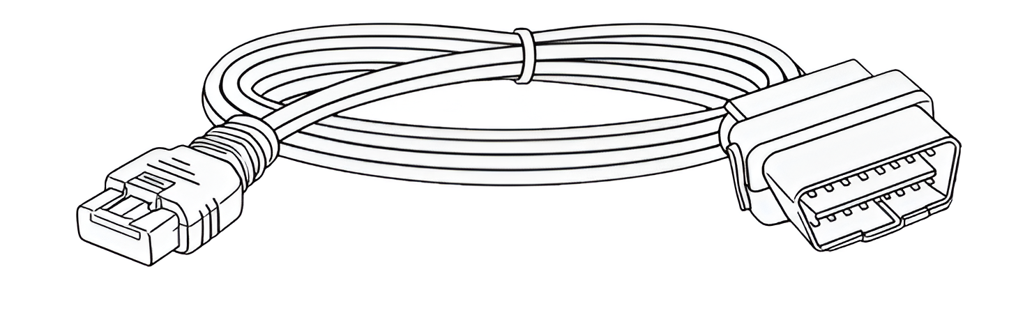
Install with the professional wiring harness
Have a qualified automotive installer choose a dry, concealed but serviceable mounting location and complete these connections using the wiring diagram below. Common locations include high under the dashboard, under a seat or in the luggage area, provided there is minimal metal above the tracker and no interference with airbags, controls or moving parts.
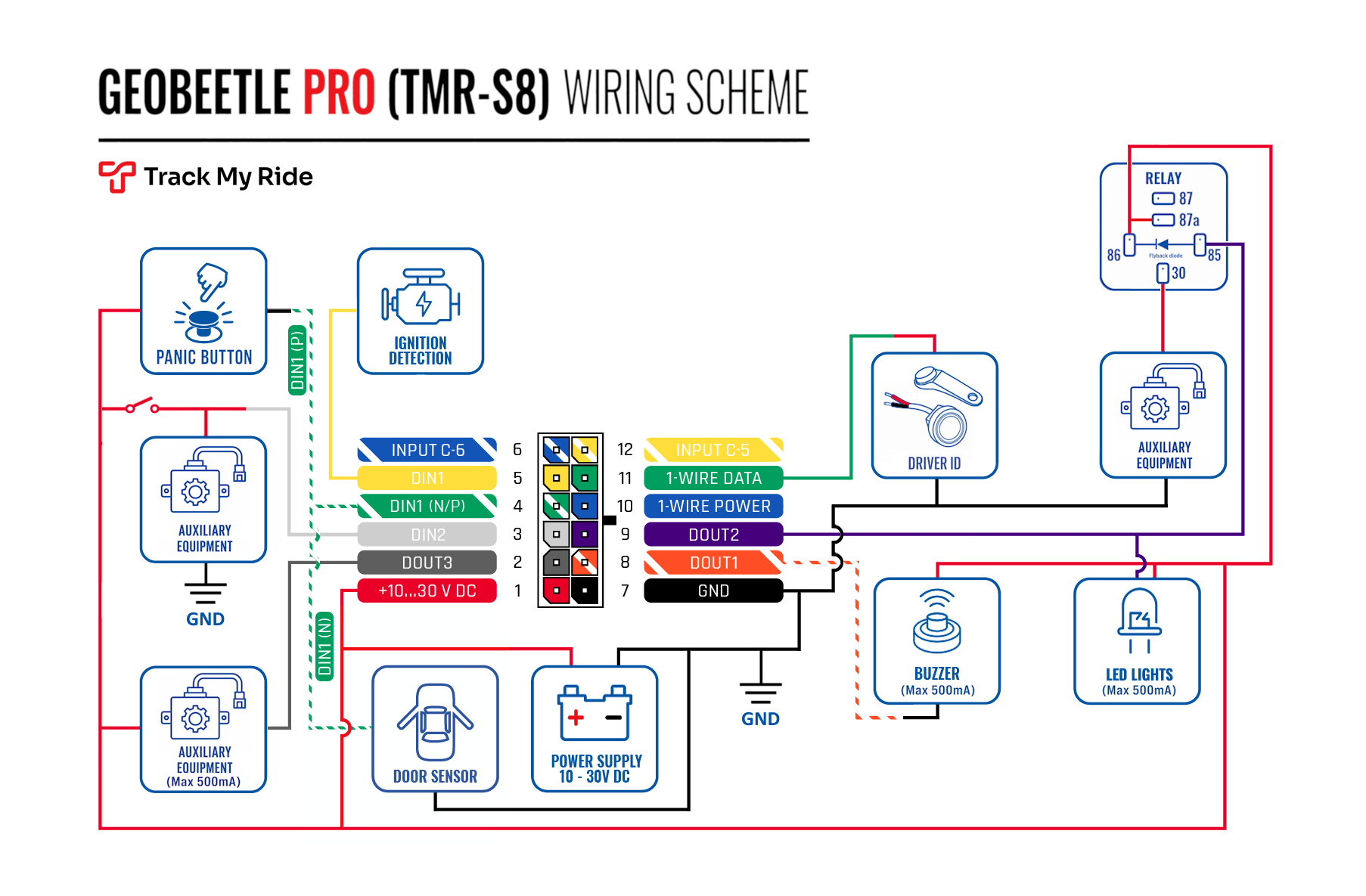
- Use a multimeter to identify a constant 10–30 V DC source and reliable common ground that meet the supplied wiring guide. Protect the source with the specified fuse. Do not probe or connect to a vehicle data line.
- Plan the cable route through existing protected channels where possible. Keep it away from heat, sharp edges, moving parts, controls and airbag deployment paths.
- Connect harness pin 1, the red +10–30 V DC wire, to the constant-positive supply. Use a suitable fuse tap or protected connection; if connecting directly to the battery, install a 2 A fuse close to the source.
- Connect harness pin 7, the black GND wire, to the same vehicle ground used by monitored accessories.
- (Optional) Connect harness pin 5, the yellow ignition input, to the verified ignition source when exact engine on/off detection is required. It should be 0 V when the engine is off and at least 12 V when the engine is on. If you do not connect this wire, the tracker defaults to engine on/off detection by monitoring its incoming power supply. It considers the engine on when that supply is at least 13.2 V.
- (Optional) For panic-button events, connect the included panic switch to Input 1 (DIN1 N/P), harness pin 4, green with white stripe. Input 1 defaults to positive sensing: connect its black wire to Input 1 and its red wire to +12 V/+24 V. Input 1 can instead use negative sensing for a ground-active circuit; configure the sensing mode in Track My Ride only after the installer has disconnected the previous switched source and rewired the input as described below.
- (Optional) For the Driver ID audible reminder, connect the included buzzer. Connect its black wire to Output 1 (DOUT1), harness pin 8, orange with white stripe and its red wire to +12 V/+24 V. The output has a maximum current limit of 500 mA.
- (Optional) For Driver ID, connect the included two-wire iButton Driver ID reader: connect its red centre-contact wire to 1-Wire Data (pin 11), green and its black outer-contact wire to GND (pin 7) or the same vehicle ground.
- The outputs have a maximum current rating of 500 mA. To switch more than 500 mA, use a relay. Connect any other inputs, outputs and accessories required for this installation. Follow the pin numbers and current limits in the wiring diagram; do not identify a connection by colour alone.
- Secure the tracker in a dry location with the side marked "Face this side up" facing the sky. It can be installed below a small amount of metal. Secure and insulate all wiring so it cannot move, abrade or contact sharp edges.
- Apply power and confirm both green lights turn on or flash. The GPS light flashes after acquiring a position; if it remains solid outdoors, choose a location with less metal above it and test again.
Using a relay on Output 1 or Output 2
The output channels are rated to a maximum current of 500 mA at 12 V. Use an automotive relay when the connected equipment draws more than 500 mA or when its load circuit must be isolated from the tracker. A relay is an electrically operated switch that allows the tracker output to control a separate circuit. A qualified auto electrician must design and install the relay circuit for the vehicle and accessory.
Output 1 is normally used by the included buzzer, if you wish to use the audible Driver Login Reminder automation. Use Output 2 (DOUT2), harness pin 9 for an additional relay unless the installer intentionally removes or redesigns the buzzer circuit. Never connect two loads to an output without confirming their combined current and circuit design.
The TMR-S8 output is an open-collector, low-side output. This type of output switches the connected circuit's path to ground rather than supplying power to it:
- Enabled connects the output pin to ground through a low-resistance path.
- Disabled leaves the output pin in its normal high-resistance state.
- Each output has the 500 mA maximum shown in the wiring diagram. The relay coil current must remain below this limit under every operating condition.
- Do not exceed 24 V on an output-controlled circuit. The tracker supply itself accepts 10–30 V DC, but that does not increase the output-channel rating.
- A relay coil draws current whenever it is energised. That current comes from the vehicle supply and passes through the tracker output to ground. A relay left energised for long periods adds continuous battery drain and keeps the output carrying the coil current.
Have the installer complete these connections:
- Choose a 12 V or 24 V automotive relay whose coil matches the vehicle supply and draws less than 500 mA. Prefer a relay or harness with built-in flyback suppression.
- Connect relay coil terminal 86 to an appropriately fused positive supply.
- Connect relay coil terminal 85 to DOUT1, harness pin 8, or DOUT2, harness pin 9. Enabling that output completes the coil's path to ground.
- If the relay does not include a built-in suppression diode, fit a correctly rated flyback diode across the coil. A flyback diode protects the circuit from the voltage spike created when the relay switches off. Connect its cathode to positive terminal 86 and its anode to output-controlled terminal 85. Reversed diode polarity can create a short circuit.
- Wire the accessory through the relay contacts using a separate, appropriately fused circuit sized for the accessory. Terminal 30 is the common contact. Choose terminal 87 or 87a according to the required normal state:
- Use 87 (normally open) when the accessory should normally be off. With the tracker output Disabled, the relay coil is off and 30 is disconnected from 87. Setting the output to Enabled energises the relay, connects 30 to 87 and turns the accessory circuit on. This arrangement only draws relay-coil current while the accessory is commanded on.
- Use 87a (normally closed) when the accessory should normally receive power and a command should temporarily disconnect it. With the tracker output Disabled, the relay coil is off and 30 remains connected to 87a. Setting the output to Enabled energises the relay, moves 30 away from 87a and turns that accessory circuit off. The wiring diagram uses this 87a arrangement. The coil draws current for the entire time the accessory is commanded off.
- On a changeover relay, 30 cannot be connected to 87 and 87a at the same time. Insulate the unused contact unless the installer has designed and documented a safe changeover circuit.
- Secure and insulate the relay, fuse, diode, harness and all joins. Keep them away from heat, water, sharp edges, airbags, controls and moving parts.
- Record whether the relay uses Output 1 or Output 2 and what it controls. Give this information to the Track My Ride account administrator.
Do not use an output as a vehicle immobiliser
Track My Ride does not support or authorise using a tracker output as a vehicle immobiliser, starter interrupt, ignition cut, fuel-pump cut, ECU cut or propulsion cut. The Track My Ride tracker and output-control service are not designed, tested or certified as an automotive immobiliser under applicable Australian Design Rules or state and territory requirements.
A remote command can be delayed, duplicated, or applied while a vehicle is moving. Stopping an engine or propulsion system while under way can reduce or remove power-assisted steering and braking, increasing stopping effort and the risk of loss of control, serious injury or death. Track My Ride accepts no responsibility for an output installed or used as an immobiliser or other safety-critical control.
Never install a Track My Ride output or relay into a vehicle's starter, ignition, fuel pump, ECU, propulsion, braking, steering, airbag or other safety-critical circuit. Ask a licensed and appropriately accredited automotive-security installer about a separately certified immobiliser that complies with the vehicle, jurisdiction and applicable Australian requirements.
Name the connected output in Track My Ride
Name the output after installation so users know what Output 1 or Output 2 controls before sending a command.
- Sign in to Track My Ride and open Vehicles.
- Find the installed vehicle and select its pencil icon to open the vehicle editor.
- Find the same channel recorded by the installer: Output 1 or Output 2.
- Leave its mode as Manual control (default) unless Output 1 uses the buzzer for Driver login reminder or Driver login beep.
- In Output 1 nickname or Output 2 nickname, enter a short description of the connected equipment, such as
Work lightorDoor relay. Nicknames can contain letters, numbers, spaces, hyphens and underscores and are limited to 20 characters. - Select Save.
- Reopen the vehicle and confirm the nickname appears beside the correct output channel before anyone operates it. Record whether Enabled turns the accessory on through 87 or turns it off through 87a so operators understand the command direction.
To test the relay, follow Configure engine detection, inputs and outputs. That guide explains how to enable or disable an output for a selected duration and confirm the queued, sent and response states in Vehicles > Events. Start with a short duration and have the installer observe the accessory in a safe location.
Configure Driver ID and the login reminder
The iButton reader records the unique ID of the key fob presented to it. Assign that Driver ID to the intended person in People so reports identify the correct driver. An unrecognised key may create an unassigned driver record for review.
To make the included buzzer remind drivers to log in:
- Confirm the iButton reader, buzzer on Output 1, and switched Ignition/Acc wire on pin 5 are installed.
- Turn the ignition or accessory circuit on so pin 5 receives 12/24 V, then allow the tracker to communicate. The option remains unavailable until Track My Ride has observed that wire powered.
- Open Vehicles, select Refresh, edit the vehicle and set Output 1 to Driver login reminder. If the option remains disabled, wait up to 15 minutes, refresh, and have the installer recheck pin 5.
- Select Save and use Review hardware tracker commands and responses to confirm the update reaches the tracker.
- Turn the vehicle ignition on. The buzzer should sound until the driver holds their assigned key fob to the reader for about one second.
- Confirm the buzzer stops and the expected person becomes the assigned driver. After the ignition has been off for at least 30 seconds, repeat the test to confirm the reminder resets.
To use a short confirmation instead of the ignition-based reminder, set Output 1 to Driver login beep and save. On a successful iButton or RFID Driver ID read, the TMR-S8 pulses Output 1 for 200 milliseconds so the included buzzer sounds briefly. This mode does not require the Ignition/Acc wire, but it does require a working Driver ID reader and the buzzer connected to Output 1. Present an assigned credential and confirm both the brief beep and the expected driver record.
Install and configure the panic switch
Input 1 supports positive or negative sensing. Positive sensing is the default and is the normal setup for the included panic switch. With positive sensing, Input 1 is active while a switched +12/24 V signal is present. With negative sensing, Input 1 is active while connected to ground. Input 2 supports positive sensing only.
The installer must use a normally open momentary switch, which closes the selected circuit only while pressed. Connect Input 1 to either a switched positive source or a switched ground source, never both. Before changing the sensing mode, disconnect Input 1 from its existing switched source; changing the software setting does not make incompatible wiring safe.
Mount the switch where the driver can reach it without looking away from the road, but where it will not be pressed accidentally or interfere with vehicle controls. The image shows one example installation; the correct position depends on the vehicle and driver.
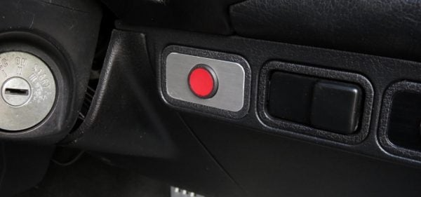
- For the default positive-sensing setup, connect a protected 12/24 V supply to one side of the normally open momentary switch. Connect the other side to DIN1, pin 4, or DIN2, pin 3.
- For an Input 1 negative-sensing setup, connect one side of the switch to DIN1, pin 4, and the other side to the same vehicle ground used by the tracker. Do not use Input 2 for negative sensing.
- Ensure the switched circuit and tracker share a common ground.
- In the vehicle editor, leave Input 1 sensing as Positive sensing (+12V active) for the default setup. For a ground-active Input 1 installation, select Negative sensing (ground active) only after Input 1 has been disconnected from any switched positive source and confirm the warning.
- Set the matching Input 1 or Input 2 action to Panic button and save.
- Configure recipients under Settings > Panic Button by following Configure Panic Button notifications.
- Warn recipients, press the switch once in a controlled test, and confirm the expected notifications arrive.
The tracker sends a panic activation over the mobile network. If the vehicle is in a coverage blackspot, delivery is delayed until the tracker reconnects; the Panic Button is not a substitute for emergency services.
Install the optional 125 kHz RFID reader
Use this section only when you purchased the RFID reader separately to replace the included iButton Driver ID reader. The RFID reader must be installed by a qualified automotive installer.
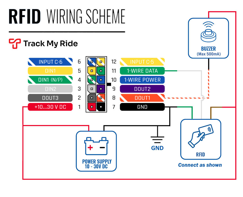
- Disconnect and remove the iButton reader if it has already been installed.
- Connect RFID reader power to harness pin 1, +10–30 V DC.
- Connect RFID reader data to harness pin 11, 1-Wire Data.
- Connect RFID reader negative to harness pin 7, GND.
- Insulate and secure every connection.
- Present each compatible 125 kHz RFID card to the reader and confirm that Track My Ride records the expected driver before relying on Driver ID records.
Activate and verify the tracker
- Download or open the Track My Ride app, then sign in or create the top-level account.
- Choose the tracker activation option and enter the Communication ID exactly as printed on the tracker's silver label.
- Complete account setup and follow the activation status shown in the application.
- Move the vehicle outdoors where it has mobile coverage and a clear view of the sky.
- Check the STATUS light. A one-second blink indicates normal operation; a two-second blink indicates sleep mode.
- Check the GPS light. It remains on while searching, blinks once per second after acquiring a GPS signal, and turns off in sleep mode.
- Open Map and confirm that the correct vehicle shows a recent location.
- Before refitting panels, drive approximately 1 km and confirm that the map shows the test route and current location. Reposition the tracker if the route is missing or inaccurate.
- For a hardwire installation, test each accessory separately: press the panic switch, trigger an action that uses the buzzer, and present an iButton key fob or RFID card to the installed Driver ID reader. Confirm the expected events and driver identity in Track My Ride.
- If a relay is installed, confirm its output nickname, send one short-duration test command, and verify that the relay and accessory return to their safe state after the duration expires.
- Refit panels only after power, GPS, route recording and every installed accessory have passed testing.
For a vehicle with a small battery, such as a motorcycle, review Sleep mode and Heartbeat in the vehicle editor. Deeper sleep and longer heartbeat intervals reduce parked power use but delay some communication. Read Edit vehicle and hardware tracker settings before changing them.
What happens next
The activated GeoBeetle Pro sends locations and configured hardware events while it has power and network coverage. Inspect its cable and connectors for wear or corrosion during vehicle servicing, and keep the tracker dry and securely mounted.
Do not open, modify, submerge or pressure wash the tracker. Do not use it if the housing is damaged or cable insulation is split; disconnect power and ask a qualified installer to inspect it.
Troubleshooting
- No lights appear: Check that the OBD-II plug is fully seated, or ask the installer to verify constant power, ground and fusing for a hardwire installation.
- The GPS light stays on: Move the vehicle outdoors and confirm that the labelled side faces the sky without thick metal above it.
- The tracker has lights but no map location: Confirm the Communication ID and activation status, move the vehicle where it has a clear view of the sky and mobile coverage, then refresh Map.
- The panic switch does not create an event: Ask the installer to confirm the input channel, its switched positive or switched ground wiring, and common ground. Confirm Input 1 sensing matches the installed circuit and that the input action is Panic button in the vehicle editor.
- The buzzer does not sound: Ask the installer to confirm that it is connected to Output 1 (pin 8) within the 500 mA limit. Confirm Output 1 uses Driver login reminder or Driver login beep as intended. For beep mode, also confirm the tracker successfully records the presented Driver ID.
- The relay does not operate: Stop sending commands. Ask the installer to check coil voltage, coil current, fused supply, suppression polarity, ground switching and whether the relay is connected to the output named in the vehicle editor.
- The relay operates but the accessory does not: Have the installer check the separately fused accessory circuit and relay terminals 30, 87 and 87a. Do not bypass the relay or connect the accessory directly to the tracker output.
- The accessory works in the opposite state to the command you expected: Stop testing and confirm whether the circuit uses normally open terminal 87 or normally closed terminal 87a. Update the circuit or operating procedure; do not guess from the output label alone.
- The vehicle battery drains while an output is active: Disable the output when safe, then ask the installer to measure relay-coil current and review how long the coil remains energised. An 87a circuit draws coil current while its accessory is commanded off; an 87 circuit draws it while the accessory is commanded on.
- The wrong accessory operates: Disable the output, make the equipment safe, and compare the physical DOUT channel with the Output 1 or Output 2 nickname before testing again.
- The iButton reader does not recognise a key fob: Ask the installer to recheck the reader's red centre-contact wire on 1-Wire Data pin 11 and black outer-contact wire on common ground, then confirm the key ID is assigned to the intended person.
- The optional RFID reader does not recognise a card: Confirm that it is a compatible 125 kHz card, then ask the installer to recheck pins 1, 11 and 7 against the RFID wiring diagram.
Continue setup
After the installation and accessory checks pass, continue to Start using your new GPS tracker and complete the first-drive check. Return to Identify and install your hardware tracker if the model or supplied cable does not match this guide.